The table below lists the properties of the four lubricants currently marketed by NPI.
| NPI-14 | NPI-16 | NPI-425 | Vitro-Lube NPI-1220 | ||
| Base Coat | Top Coat | ||||
| Pigments | MoS2 and graphite | MoS2 | MoS2 | MoS2, Graphite (proprietary) | MoS2, Graphite |
| Binder | Phenolic | Phenolic | Polyimide | Ceramic | Phenolic |
| Solvent | Denatured Alcohol | Denatured Alcohol | Ethyl Alcohol | Ethyl Alcohol | Denatured Alcohol |
| Cure Temperature | 1 Hour at +300°F | 1 Hour at +300°F | 1 Hour at +300°F and 1 Hour at +575°F | 1 Min. After Reaching +975°F | 1 Hour at +300°F |
| Total Thickness (inches) | 0.0003 to 0.0005 | 0.0003 to 0.0005 | 0.0002 to 0.0004 | 0.0004 to 0.0006 | 0.0002 to 0.0003 |
| Outgassing TWL-% | 0.85 | 0.91 | 0.82 | 0.0039 | |
| Outgassing VCM-% | 0.0115 | 0.005 | <0.01 | 0.0147 (Both Base & Top Coat) | |
| Solar Absorptance | 0.827 | ||||
| Total Normal Emittance | 0.823 | ||||
| Density-#/cu. in. | 0.072 | ||||
| Surface Restivity Ohms x 106 (per ASTM 257) | 11.56 | 50.65 | |||
| Temp. Limitation* | +300°F | +300°F | +500°F | +700°F | +700°F |
| *This temperature limitation is for long term usage. |
The graph below shows the relative wear life of bonded lubricants where data is available.

Dry Film Lubricants in automotive applications provide a unique challenge. In 1995, NPI was involved in a test program conducted by Loyola Marymount University evaluating the effects of three dry lubricants on automotive valve train wear resistance.
Scuffing wear occurs as the cam slides across the lifter face where the rotating motion of the camshaft is converted into the linear motion necessary to drive the cylinder head valves. This scuffing is caused by localized microscopic bonding between the skidding surfaces. It was determined that this can be minimized by using dry film lubricant coatings to increase the boundary lubrication depth adjacent to the contact area.
Introduction
The operating conditions at the contact line between the rotating camshaft lobe and the reciprocating valve lifter in an automotive engine are extremely severe. High loading forces, high sliding velocity and high friction between the cam and lifter make this interface one of the most wear-prone areas in an internal combustion engine. Scuffing wear is the common wear mechanism. Fortunately, judicious material selection and processing, excellent cam surface alignment and proper lubrication can minimize scuffing wear and provide long engine life.
Since proper lubrication is essential for minimum wear, virtually all production four-stroke internal combustion designs provide for the splashing of copious amounts of oil in and around the camshaft during continuous engine operation. However, during engine start-up the situation is different since splashing cannot occur until oil is first pumped upward from the oil pan located at the bottom of the engine. In the seconds before the oil pump reaches full pressure, thereby filling oil galleys and running clearances, camshaft lubrication is scant. During this time, dry film lubricant coatings can best protect the engine.
Investigation
Testing was performed to determine the resistance of various dry lubricant coatings to scuffing wear at the camshaft-to-follower interface. Mating hydraulic lifters and valve springs from a V-8 engine were employed. Camshafts used in the tests were made of alloyed gray iron (ASTM A-159 Gr. G4000D, SAE J431C Gr. G4000D), with a lobe surface hardness of Rc 50. The lifters were made from hard enable iron, having a minimum hardness of Rc 55. An unlubricated camshaft was tested to serve as a control. Various camshaft surfaces were individually treated in one of three ways – by Parkerizing (a patented type of manganese phosphate coating), by spray applied graphite coating, and by molybdenum disulfide coating. Coatings were applied to the camshaft surfaces in accordance with manufacturers’ specifications. The molybdenum disulfide coating was NPI-16 manufactured and applied by National Process Industries, Temecula, California.
To measure the cam-lobe-to-follower friction coefficient, the camshaft was supported in the lathe on centers coincident with the camshaft rotation axis (figure 1). Oil was applied to the center contact areas to minimize bearing friction. The lathe headstock was adjusted to press the follower in its fixture against the cam lobe, which was positioned at the top dead center.
Next a string was wrapped around the axis of the camshaft and attached to a weight. By varying either the weight or the follower spring compression, the assembly could be adjusted to equalize the weight and the camshaft geometry, the follower contact force and the torque could then be calculated.
Results
Coefficients of static friction at the camshaft-to-follower interface, correlating to each of the various coatings are displayed in Table 1 and Figure 2. As recorded in Table 1, the coefficient of static friction for the NPI-16 coated interface was considerably lower than that recorded at the unlubricated interface. Experimental results showed that NPI-16 provided the most significant resistance to scuffing wear of all the tested coatings. The follower face profile was visibly affected only after 12 hours of testing and no visible effect was noted at the cam lobe surfaces; this is due to the high thermal resistance of the coating. Even though approximately 40% of the coating had mixed with the engine oil and worn away from the interface after 4 hours of testing, it was observed that the remaining coating did not further disappear; it remained entrained at the interface for the duration of the test. More specifics related to this test program can be obtained by contacting NPI sales personnel.
Table 1 Coefficients of Static Friction for Each Camshaft-to-Lifter Interface, by Lubricant Type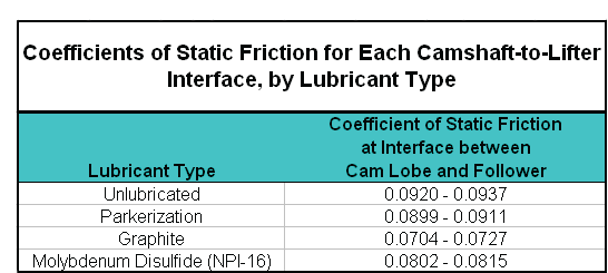
Figure 2 Histogram of Coefficients of Static Friction for Each Camshaft-to-Lifter Interface, by Lubricant Type
NPI Recommendations
NPI coatings provide a back-up and second layer of protection that will lubricate during extreme operating conditions, high loads/contact stresses and at high temperatures. Not only should Valve Train Components be coated but all internal engine parts where optimum performance is desired; all Moving Mechanical Assemblies (MMA’s) such as:
- Bearings
- Gears – rear end or transmission
- Pistons
- Rocker Arms
- Fuel Pumps / Bertha Spacers
- Crankshafts
- Valves and Valve Springs
All should be coated to provide that extra edge during competitive operation. As we have seen with the Automotive Valve Train test results, with proper lubrication the benefits are unmistakable. You can expect to see:
- Less wear
- Reduced friction
- Increased power
- Longer part life